Temperature Controlled Fan Project using Arduino Circuit Diagram Here in this temperature controlled dc fan project, a 10K NTC thermistor is used. To turn on the DC fan, we use an IC 741 op-amp as a voltage comparator. Its inverting input (pin 2) gets an adjustable voltage through the potentiometer while its non-inverting (pin 3) input gets voltage through a potential divider involving a 1KΩ resistor and In this article, we learned about, how we can make a temperature-controlled fan circuit. Using an Arduino, DHT11, and few other components. Which can be used pretty much any place where temperature needs to be maintained at specific levels. Like in some industries, houses, etc.
When the temperature rises its resistance is decreased and increases when the temperature is low. The other important component of this circuit is a transistor. we have used a BD139 transistor it is working as a switch for the fan in this circuit. This circuit is inexpensive and easy to build as it is using only a few components.

Temperature Controlled Fan with LM35 and Arduino Circuit Diagram
Temperature Controlled Fan Circuit Diagram. The complete circuit to build the temperature controlled fan using arduino and lm35 project is given below, we have used fritzing software for making most of the circuit diagrams. The fan and the plug were later added using photoshop. The diagram consists of an arduino,a relay, an lm35 sensor, an AC fan, and a plug.

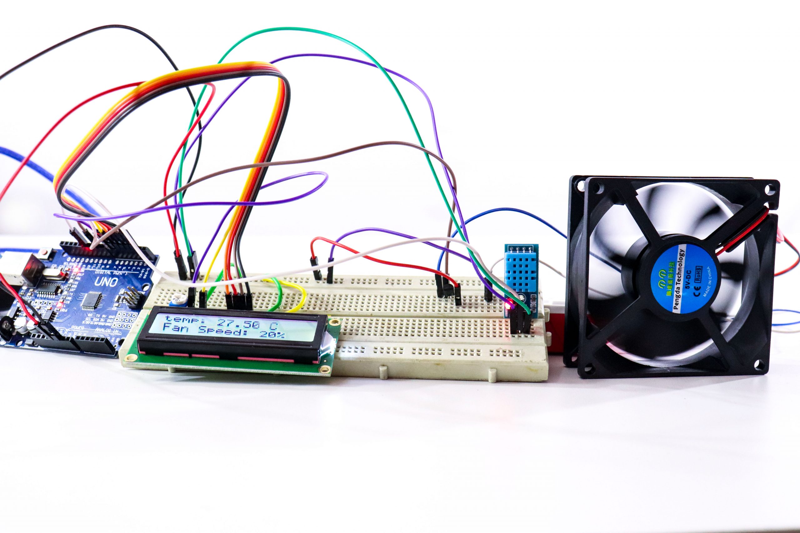
The second temperature controlled dc fan circuit project discussed below automatically senses the ambient temperature and adjusts the fan motor speed to keep the surrounding temperature under control. This automatic processing is done through an Arduino and a temperature sensor IC LM35. By: Ankit Negi. OUR OBJECTIVE: 1).
Temperature Controlled DC Fan using Thermistor Circuit Diagram
This circuit uses a thermistor as a sensor, the thermistor resistance decrease when a temperature increase. When the temperature increases the thermistor resistance decrease until the voltage set point that adjusts by potentiometer higher than Vgs threshold, MOSFET change to ON state and make a 12 volts fan start and rotating speed faster when a temperature hotter.
