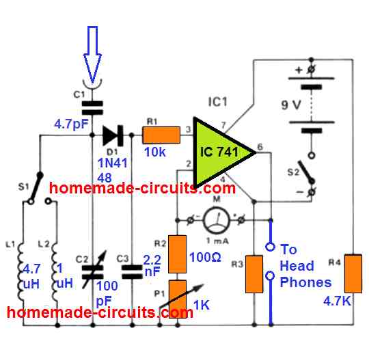
Full Circuit Diagram with Component Layout To test the circuit, hold the antenna near an RF source (e.g. a radio or cell phone), and the LED should light up when it detects the signal. It is essential to be cognizant of the safety risks that are associated with RF radiation and take proper measures when constructing or using an RF detector.

The diodes may be small signal germanium or silicon although Schottly diodes are preferred. Assemble the components on a small piece of printed circuit board. Use wire probes or a BNC coax socket at the RF input with very short leads to the PCB.

Simple RF Mobile Signal Detector Schematic Diagram Circuit to detect ... Circuit Diagram
This simple RF signal detector circuit can be used to trace the presence of RF signals and electromagnetic noise in your residential area, office or shop. It can be a useful tool while testing or designing RF circuits. It can also be used to detect electrical noise in your premises.
Very cool RF mobile signal detector from simpletronic - the circuit is main driven by high frequency RF transistor up to 6 Ghz maximum. It can easily detect low frequency and high frequency electromagnetic and RF signal.
3 Simple RF Detector Circuits / Radio Signal Field Detector Circuit Diagram
However, for this simple transistor RF detector to work a super clean, alcohol-washed veroboard would be required, under reduced humidity circumstances. Temperature variations, light beaming on the transistor, and other inbound signals would almost certainly still trigger the circuit and could make it unstable.
