amps to compare two varying Circuit Diagram Equivalent Circuit of an Ideal Operational Amplifier. Op-amp Parameter and Idealised Characteristic. Open Loop Gain, (Avo) Infinite - The main function of an operational amplifier is to amplify the input signal and the more open loop gain it has the better. Open-loop gain is the gain of the op-amp without positive or negative feedback and for Q point is basically a DC value (on DC load line) over which the ac signal is superimposed for the faithful amplification. This value Q point is generally a mid-value to get the maximum signal efficiency. Here we can set the Q-point in case of audio amplifier to adjust the signal to power efficiency ratio.

In a linear op amp, the output signal is the amplification factor, known as the amplifier's gain multiplied by the value of the input signal. A simple comparator can be created using an op amp

Operational Amplifier AC Amplifier : 6 Steps Circuit Diagram
CMRR: Ideally op-amp should have infinite CMRR, Common Mode Rejection Ratio so that common noise voltage in the output becomes zero. Slew Rate: Ideally op-amp should have infinite SR, slew rate so that any change in the input voltage simultaneously changes the output voltage. Basic terminologies of an op-amp - 1.

Mixers use op-amps to combine multiple audio signals, while equalizers employ op-amps to adjust the frequency response of an audio signal. Filters, built using op-amps, are used to remove unwanted noise or frequencies from audio signals, ensuring clear and high-quality sound reproduction. Examples of op-amps in audio circuits: Programmable gain signal amplification via the internal feedback resistor network. • Differential Amplifier using two op amps: Differential input voltage amplification with a rejection of the common-mode voltage. • Instrumentation Amplifier using three op amps: Differential signal amplification with high input and low output impedance.

Amp Circuits : 7 Steps Circuit Diagram
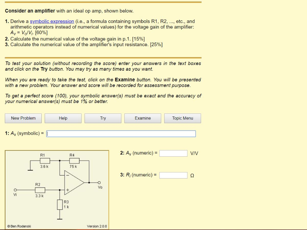
inputs the same. That is, the op amp tries to make v− + =v v + −. The second approximation is that the inputs of the op amp draw no current. Using Kirchoff's current law and the assumption that no current flows into the op amp gives: R2 v v R1 − −v v in = out − −. Recognizing that (from the first assumption above) gives the gain

Figure 7 shows a voltage to current converter using an op-amp and a transistor. The op-amp forces its positive and negative inputs to be equal; hence, the voltage at the negative input of the op-amp is equal to Vin. The current through the load resistor, RL, the transistor and R is consequently equal to Vin/R. We put a transistor at the output
